

How the Wind Uplift Test Setup Works
The test setup for the wind uplift test consists of different components and is similar to a test roof setup.
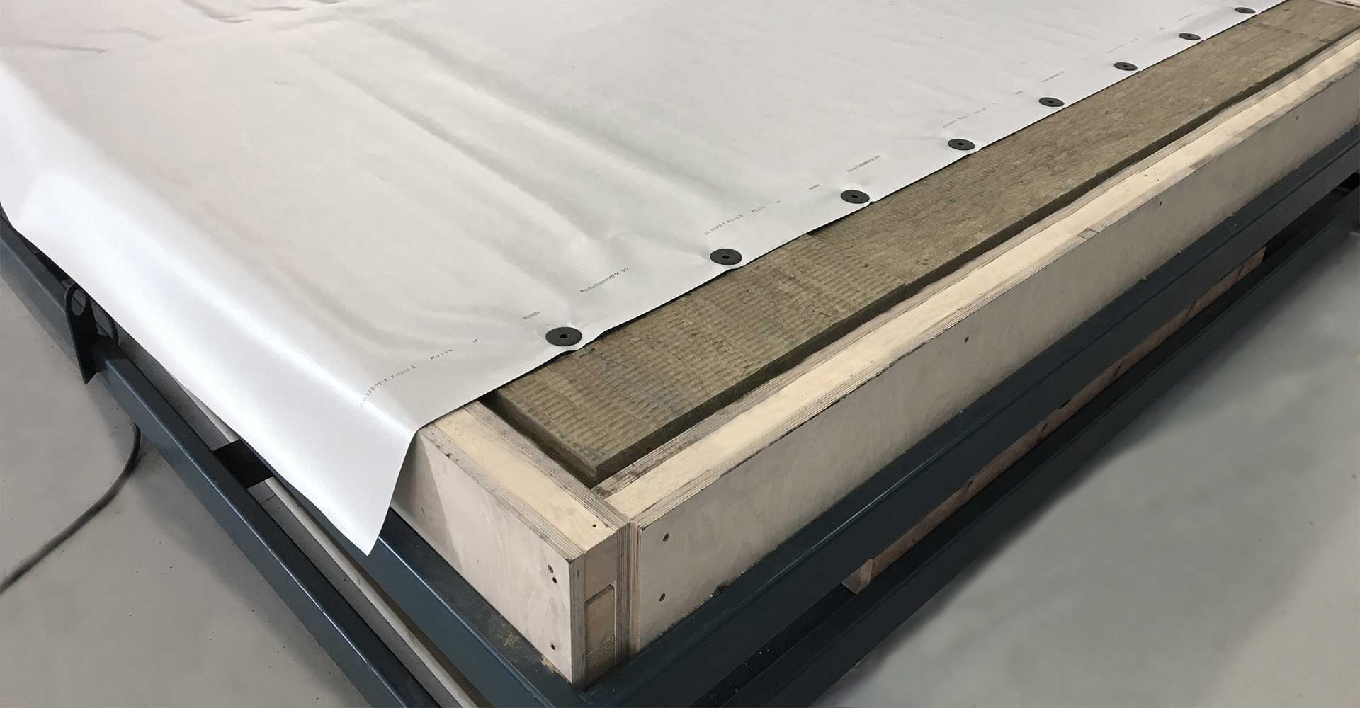
Components Used Within a Flat Roof Wind Uplift Test
For example, a wooden frame is used, which forms the external dimensions of the test item. The frame has the same dimensions as the cover, in which wind suction is generated later. Within this frame, there is a steel trapezoidal profile. On top there is 10 cm of insulating material. The roofing membrane is placed on the insulating material and is attached in a defined grid.
Why Lower Strength Materials Are Used During Wind Uplift Testing
The material of the steel trapezoidal profile and the insulation is chosen so that it has a lower grade or is in the area of the most unfavourable property. This guarantees that the test results can also be applied to steel sheets with trapezoidal corrugation that have higher strength properties and insulation with higher compression strength.
How Artificial Wind Suction Cycles Are Simulated
Once the test roof set-up has been finished and the overlap of the roofing membrane has been welded, the test is performed under a cover. Under this cover, artificial blasts of wind are now generated. They cause the roofing membrane to bulge upwards.The quantity, frequency, and intensity of the blasts of wind are specifically fixed.
Wind Load Cycle Duration and Test Procedure
A blast of wind lasts 8 seconds and consists of a phase in which the wind suction is built up. This is then maintained for 2 seconds and then further reduced. The next wind suction then begins immediately afterwards. A cycle ends after 1,415 wind blasts. The force is built up slowly during a cycle. The test is performed until there is a failure in the system. A wind uplift test according to EAD or DIN 16002 can take up to three days.